First pass with small electrode holders and Lexan plate.
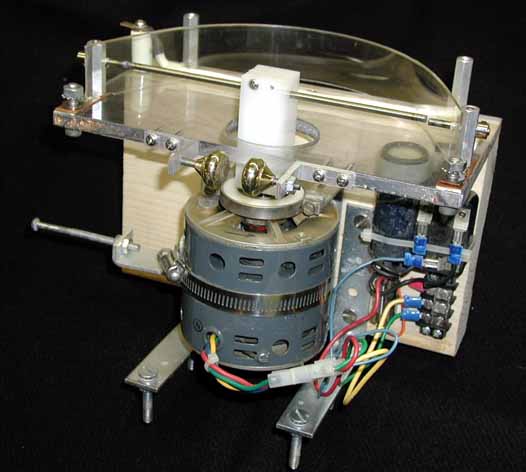
May 2004 - I finally got to building a synchronous rotary spark gap (SRSG) using a 7" long 5/32" dia tungsten welding rod in place of a conventional disk. Terry Blake first demonstrated this configuration, which has come to be known as a propeller gap (see Terrys RSG page). The propeller configuration offers a much lower rotating mass than a disk, so a much smaller motor may be used, and is much simpler to construct. For attaching the rod to the motor shaft, Terry used a press-fit through the arbor, backed up by set-screw collars. I didnt care for the collars, since if the set screw loosened from the vibration, it will fly off the handle and cause a crash. I made an arbor out of Delrin, but rather than relying on a press-fit to keep the rod in place (which actually was quite secure), I slit the end of the arbor down the middle with a band saw and added two screws to create a clamp. To hold the stationary electrodes I initially used a pair of hex aluminum spacers with a set screw, plus a set-screw collar as a backup in case the main set screw loosened (both the rod and set screw are very hard so the screw doesn't dig in well). I found that the stationary electrodes and hex spacers got very hot and was concerned that the Lexan base could soften, so I rebuilt it with a phenolic support plate and aluminum plate electrode holders (probably overkill).
The motor is a 3600RPM synchronous unit removed from an old Teletype machine.
A safety gap in parallel with the SRSG is mandatory and keeps the gap from entering the "presentations at zero-crossing" mode (see waveforms below) and resulting excessive voltages, should the phase be adjusted too late. The phase adjustment procedure is with the coil running at full Variac, advance the phase until the safety gap begins to fire, then back off just a tad. The optimum phase is dependant on the Variac setting.
First pass with small electrode holders and Lexan plate.
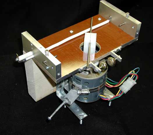
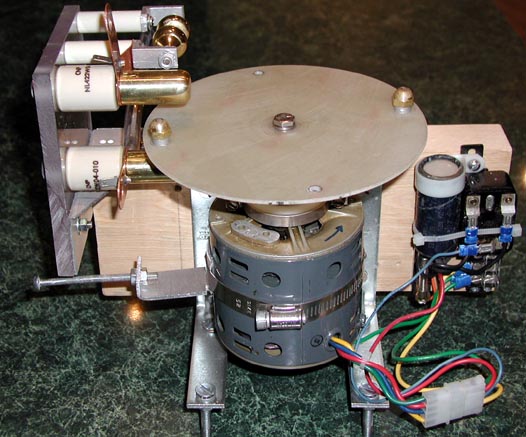
Second pass
with massive electrode holders and phenolic support plate. Socket head screws
to secure the stationary tungsten rods proved much more secure than set screws,
since more torque can be applied to them. The lever to mechanically adjust the
motor phase by rotating the motor in its cradle is visible - since replaced with
the electronic phase adjuster.
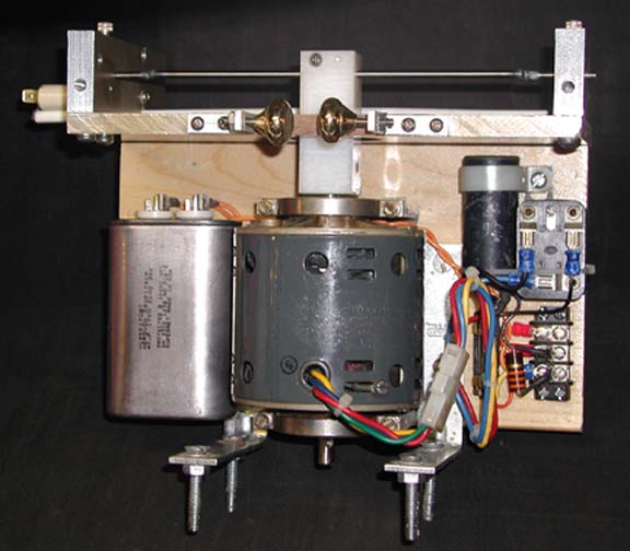
Replaced the mechanical phase adjustment lever with electronic phase adjuster
cap.
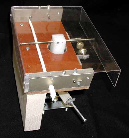
Shows the Lexan shrapnel shield. I use
Faston terminals for the low-current connections to
the NST filter.
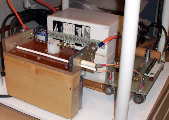
Note the
string of thirty nine 2.0Meg 1/4W resistors (78Meg total) across the upper
Maxwell cap to bleed off any residual charge, should the normal discharge path
through the NST be broken. With a .04uF cap, this has a time constant of 3.2
seconds, so things should be pretty safe within about 15 seconds.
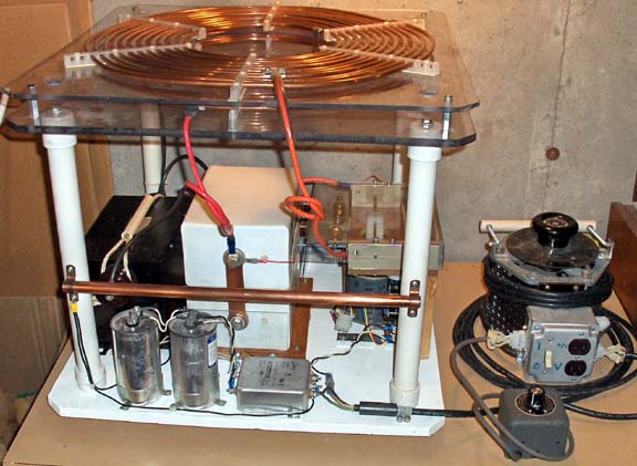
Above shows the main 15 Amp Variac which powers the NST, as well as a smaller 2
Amp Variac (in gray box) used to remotely adjust the phase of the sync gap
motor*. Along the lower edge of the plywood base are a pair of 120uF motor run caps (240uF total)
providing power factor correction for the NST, a 30Amp EMI filter, and a
ferrite EMI filter on the incoming AC cord. The copper pipe segment
(tied to RF ground) above the AC components is an attempt to shield them from a
streamer-strike.
* A technique pioneered by John Freau. Using the mechanical lever to adjust the motor in its cradle, achieved 3.5msec of phase adjustment. With the 2A Variac and a 37uF cap, achieved 4.0 msec adjustment. With a 2A variac and a 48uF cap, achieved a 4.5 msec adjustment. In practice, I use only perhaps 1/3 of the 4.5 msec range, so I could have used less capacitance.
AC circuit schematic for the RSG phase controller, AC wiring, and RSG motor & starter notes:
Here are a couple of pictures of my previous (May 24, 2001) attempt at a synchronous RSG. It used the same 3600 RPM Teletype motor and a .09" thick x 6.12" diameter G10 disk. Four 10-32 brass acorn nuts are used for the rotating electrodes. The fixed electrodes are lengths of 3/4" diameter brass stock. A safety gap made from brass drawer knobs is wired in parallel with the main electrodes. A stainless steel hose clamp holds a bracket to the side of the motor housing and this is used to rotate the motor within its cradle to adjust the phase of the gap. This can be done while the gap and coil are running, but I had to replace the hard rubber motor mounts with a pair of custom-machined white delrin mounts. The original mounts were slightly eccentric and would cause the gap clearance to shift when the motor was rotated in its cradle. Total gap clearance at presentation is about .04".
The photo below shows a pair of 120V/500W halogen bulbs wired in place of the primary coil as a means of dummy-loading the tank circuit. (I since use three lamps in series) This allows the phase of the gap to be set by looking for the brightest illumination of the lamps, without those pesky streamers lapping at you.

What I had hoped was that there would be an obvious peak brightness in the halogen bulbs at a certain point as the motor was rotated in its cradle, with the brightness diminishing on either side of the sweet spot. What I observed was somewhat different. As I adjusted the phase from firing just prior to peak charging voltage to just beyond peak charging voltage (see waveform below), the lamp brightness increased as expected. Then if I advanced the phase just slightly later than the first waveform shows, the gap firing became unstable, and in most cases, stopped altogether (see lowermost waveform).
In both waveforms, the vertical scale is 11.9kV/div. The scope was triggering on the AC line, so the sync point relative to the disk rotation is the same in both waveforms. In the lower waveform, the gap is not firing because the phase of the cap voltage has shifted such that the gap presentrations are occurring at or near the zero voltage crossings. In the waveform above the peak charging voltage is 26.2kV, and the gap fires at a cap voltage of 25.3kV. In the waveform below, with the gap not firing at all, the cap voltage is peaking at 29.7kV, not a healthy situation!
It's not intuative, but when using an LTR-sized cap, the peak power will be obtained when the gap fires at a point somewhat beyond the peak charging voltage, and not AT the peak charging voltage as one might think.
Why the phase of the cap charging voltage changes so radically when the firing phase shifts beyond a certain point is unclear. I have one theory. One of my design goals for this gap was to keep all electrode surfaces as rounded as possible to minimize the separation of the gaps when they fire. The unfortunate side effect of these larger electrodes is to increase the effective dwell time of the electrode presentations. Since the peak cap charging voltage is occurring prior to the gap alignment, this higher voltage may cause the gap to break down just a bit early, and this may throw the charging cycle "out of whack". I'll have to do some MicroSim'ing to get a better handle on this "out of whackness". I wish it were so easy to replace my 3/4" brass electrodes and acorn nuts with some 1/8" tungsten rods for comparison.
Epilog - the propeller gap worked MUCH better.