Update - March 2, 1999 - Failure analysis - See bottom of this page
Note: One of the rolled poly capacitor described below failed after a 7-8 minute near-continuous test run. The surface of the PVC container near the ends of the internal roll felt slightly warm to the touch prior to failure. A post mortem dissection revealed a dielectric puncture along the recessed edge of the foil, and slight discoloration of the poly elsewhere along the recessed foil edge, suggesting either that 7-8 minutes is too long to run continuously, or that the .04" poly was too thin.
It should be noted that the capacitor failed with a loud BANG, rupturing one of the end caps and spewing oil, as the container had no provisions for pressure relief. I've deleted the text below suggesting no relief mechanism is necessary and have learned my lesson. I still believe the extended foil construction is mechanically and electrically sound, and will add more to this page after I figure out what to do next.
Below is a diagram of my latest tank capacitor. Most rolled capacitors have each terminal's connection to either the inside (at the center of the roll) or outside end of the rolled plate. This results in unwanted series inductance, or ESL, in series with the capacitor, compromising its pulse-discharge characteristics. The capacitor described below is a rolled poly unit, featuring extended foil construction. This means that each of the plates is connected to its output terminal along the entire length of its long edge, resulting in much lower ESL. The design is based on a description published on the Tesla Coil Mailing List by Fr. Thomas McGahee.
Having a 15KV/60mA NST, I needed a .01 uF capacitor to match the NST to give resonant charging and extract maximum power from the NST. I also happened to have exactly one 4 ft x 8 ft sheet of 0.04" thick LDPE (low density polyethylene). I had heard that it's best to construct 2-3 identical capacitors (of 2-3 times the desired total capacitance and 1/2 to 1/3 the total dielectric thickness each) wired in series, rather than make a single unit, as this subjects the dielectric to much less stress. Since my first single capacitor using two layers of .040" poly suffered a punctured dielectric, the series approach sounded good. Since I only had enough poly for two units, that would have to do.
Capacitance formula for a rolled cap: C = .224 (k) (A) (2) / T, where C is capacitance in pF, k is dielectric constant of poly (2.2), A is the area of each foil plate in square inches, and T is thickness of poly dielectric. For my case, the alternate foil sheets overlap by 9"wide by 92" long, so A=9x92=828sq-in. C = .224 x 2.2 x 828 x 2 / .04 = 20402 pF or .0204 uF per unit. Two units in series would be .0102 uF.
The inner core of the capacitor roll is a 14-inch length of 2-inch schedule 40 PVC pipe. I chose to plug the ends with machined disks of lexan, press-fitted and cemented in place. This was only to minimize the amount of oil needed to later fill the capacitor and is not functionally necessary. The outer container is 4-inch schedule 35 SDR PVC drain pipe and end caps. The 2-inch pipe was selected to provide a tight fit for the completed roll into the 4-inch pipe, also minimizing oil use.
Cut the poly sheet into four 12" x 96" strips. Two strips will be used in each of the two series connected capacitors. Since there's only one layer of poly between the plates, any punctures or scratches would be fatal to the capacitor, so inspect the poly carefully. Cadillac Plastics had done a good job packing it and I found no defects. For the plates I used household aluminum foil, 12" width. For the extended foil construction to work, aluminum flashing would have been too stiff. Heavy-duty gauge foil might have been less fragile to work with, but since it only came in 18" width and I needed 12", it was easier to be careful than to cut down the 18" width. It is also vital that the foil edges be very straight and uniform in width, more on this later.
Rather than using a pair of continuous foil plates, cut each foil plate into multiple 12" x 16" long segments. Place a foil segment on top of each poly strip. As the poly and foil are both 12" wide, offset the two by 1.5" on the long edge. Use an 8-foot straight edge to mark the 1.5" margin on the poly sheet, do not simply make several dots 1.5" in from the edge and connect the dots. This is to ensure a perfectly straight foil edge when rolling, as the poly edge will not be visible. The 12" edge of each foil segment nearest the inside of the roll end is taped in place on the poly. I used two small bits of kapton tape. The next 16" foil segment is placed 15.5" from the start of the first segment and taped to the poly, underneath the previous foil segment. Each segment overlaps the previous one by 0.5", and each is held in position by tape, but only on the 12" side nearest the inside end of the roll. The reason for the multiple segments is to allow the plates to shift as the assembly is being rolled, without shifting the position of the unrolled foil segments. Unlike conventional rolled caps, there is no current flow through the long axis of the plates, so they needn't be continuous.
After the two poly strips have their foil segments taped in place, stack the two assemblies such that the foil overhang goes to the left for one and to the right for the other. Align all 4 edges of the poly to be coincident. Now center the 2-inch PVC core pipe on top of the taped-end of the foil/poly assembly and begin tightly rolling it. This is a two-person job. Take careful note that two foil edges on the roll are perfectly in line with the rolled foil edges. If the foil edges become concave or convex, it's because the core pipe wasn't perfectly perpendicular to the foil edge, and you'll have to unroll and start over again. This part requires great patience and I know of no shortcut towards keeping the roll straight. When the roll is complete, secure it with tape around its circumference.
Drill a hole for a #10 screw in stainless steel hose clamps, about 1.5" from the worm-screw towards the free end. Neatly fold down the foil hanging over the ends of the poly onto the PVC pipe as shown in the illustration, and clamp it down with the hose clamps. With a sharp Exacto knife, on both ends of the roll, slice several radial cuts through all layers of foil from the 2" pipe to the outermost layer of poly. This is to allow passage of air and oil during the vacuum/oil fill procedure.
As indicated in the diagram, solder the inner brass nut, copper or brass terminal strap (3/4" wide w/ a #10 and a 1/4" hole about 2" apart), and brass washer to the 1/4-20 brass terminal stud. Pre-tin each of the mating surfaces and compress everything with a stainless steel nut (where the neoprene washer would go, so solder won't stick) and tighten the nuts as you heat it up. If the gaps between the threads and nut and strap and washer are not completely filled with solder, the unit may later leak oil.
The 1/4" lexan disk on one of the end caps serves two purposes. It provides a surface that can be tapped to accommodate the threads of the barbed vacuum hose fittings (PVC is difficult to tap), and it gives a clear window to monitor the oil filling process. I left a 1" margin for the PVC cap and used PVC cement to glue the two pieces together on this margin.
After the end caps and studs are ready, assemble the roll, end caps, and 4" PVC container, using PVC cleaner and lots of PVC cement to glue the end caps. Don't forget the neoprene washers! Wait several days for the cement to dry before attempting to oil fill the unit. It would help if after 1 day, a mild vacuum was drawn and maintained for a few days to help remove the solvent vapors from the cement.
The tight-rolled construction of this extended foil design makes removal of air bubbles impossible without the use of a vacuum pump. Fortunately I was able to borrow one from work. My vacuum "circuit" had things in this order: a soda bottle oil reservoir, an oil valve, my two capacitors in series, an oil overflow catch jar, a vacuum valve or switch, and the vacuum pump. Be sure the hose in the oil reservoir goes to the bottom and stays there, and that there's enough oil in the reservoir. I needed 2 1/2 pints of mineral oil (from the laxative section of any drug store) for my two units. Make sure you have well in excess of what you need.
Open the vacuum valve, close the oil valve, and start up the pump. Slowly open the oil valve and observe the oil flowing into the first capacitor. After the oil line between the valve and the first capacitor is free of air bubbles, close the oil valve and continue the vacuum pump for several more minutes. Now slowly open the oil valve and observe the oil filling the first capacitor, then the second capacitor. After both are full, close the vacuum valve and shut off the pump. The pressure in the capacitors should now be at atmospheric pressure. If there are any air bubbles visible in the lexan windows, try to remove them through the oil-filled tubing. Each of the two completed capacitors should measure about .02 uF, or .01 uF for the two in series.
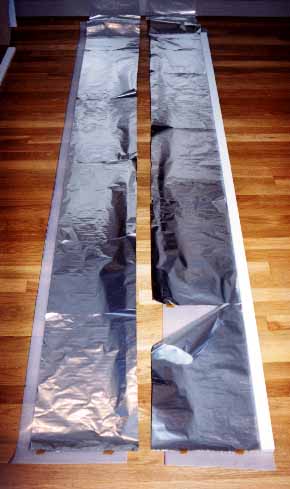
This shows each of the two strips of poly for one capacitor, with the segments of aluminum foil taped in place. The white wooden strip on the right edge is spaced 1.5" from the long edge of the poly and ensures that the foil is applied in a perfectly straight line. Note also that only the lower edge of each sheet of foil is taped to the poly. I used a brown-colored kapton tape. The lower end will be the inside of the roll.
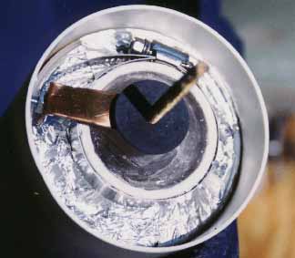
The PVC end caps are ready to go on. Note what a snug fit the roll is inside the 4" pipe.
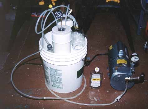
Here's the vacuum pump and hookup.
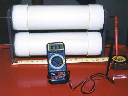
Here's the two completed caps, wired in series, being measured on my capacitance meter. 10.07 nF, or .0107 uF, not too far off target!
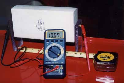
For comparison, this is the capacitor I purchased from Fair Radio Sales for $99. Rated .01 uF, 100KVDC, this is probably the cheapest ready-made capacitor one can buy off-the-shelf, and it served me well. The only problem is that it gets slightly warm after a few 30-second runs, so I suspected I might get better results building my own rolled-poly cap (above). So far they seem to perform comparably, although I am proud to be able to say that I rolled my own. And I swear, they really do both read 10.07 nF, this was not a camera trick or a meter anomaly!
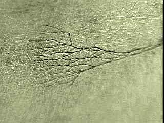
As mentioned at the top of the page, one of these two series-connected rolled caps failed after about 7 near-continuous minutes of operation. The exterior of the PVC container felt warm to the touch in the areas corresponding to the edges of the foil. A post-mortem dissection revealed a dielectric puncture about half way along the long edge of the foil. A very narrow, very slight discoloration or frosting on the dielectric was observed on much of the poly, just under the edges of the foil, but not just in the area of the puncture. A sample of the poly was microscopically analyzed by Scott Hanson. Scott sent me a preliminary photograph of the etching, shown below. The overall length of the etching is 1/4" - 3/8". The foil plate was on the left side of the pattern.