I suspect most newcomers to coiling are frustrated in trying to determine what constitutes an appropriate protection circuit to protect one's transformer. The archives are full of conflicting advice, much of it justified only by the anecdotal "I've (or I haven’t) been using blah blah blah, and I haven't lost a transformer yet". But transformers die all the time in Tesla service. Does a circuit exist that will guarantee eternal life for an NST?
Probably not. I suspect that most NST failures occur because people find that the wider they open their static gaps, the better their coil performs. Then their NST dies and they wonder why. Static gaps MUST be set to a width that is less than what will deliver the best performance. There is no simple table or formula stating that for an X kV NST, the gap must be set to Y inches. A static gap must be experimentally set such that when only the NST is wired across the gap, the gap will -just- start to arc when the variac is set to maximum. This sets the gap breakdown voltage to the maximum voltage that the NST is designed to withstand. OK, maybe just a smidge wider if you want to live dangerously, but I didn’t tell you this. It’s not obvious, but if the gap is set too wide, the voltage generated in an operating Tesla primary circuit can FAR exceed the open-circuit voltage of just the NST, and this is a guaranteed NST-killer.
No protection circuit will save you if you set the main gap too wide.
It has been said that NST's are not designed to work continuously at the faceplate voltage - that the 15KV or whatever is needed only briefly to ionize the neon gas, at which point the voltage is clamped by the lamp to something on the order of several hundred volts. No way to protect against that, although minimizing the spark gap width, while hobbling performance, will also limit the maximum voltage seen by the NST. But other mechanisms exist in an operating coil that generate high frequency voltage spikes twice as high as the faceplate voltage, and these can be filtered out.
Much of the advice in the archives suggests the use of chokes plus bypass capacitors to form a low pass L-C filter. I also see frequent advice advising the use of only series chokes, without the use of bypass capacitors. One cannot form a low-pass filter without a capacitor to ground, and the self-capacitance of the transformer's secondary doesn't count, as this would be a distributed capacitance, with an effective value of zero at the output terminals.
Since I knew that L-C networks do make a good low-pass filter, I began by making some 600 pF bypass capacitors out of .09" thick copper-clad G10. I had to cover all plates with Vaseline to inhibit corona. The thickness of the dielectric was adequate but the 0.75" margin around the perimeter arced over after a few months of use. Increasing the margin to 1.00" dropped the capacitance to 450 pF per unit and I've not had any arcing problems with these capacitors since.
In parallel with each bypass capacitor (from each NST terminal to case/RF ground) is a safety gap. Safety gap construction is not critical since it's (hopefully) not something that fires too often, but it's vital since it's the last line of defense. The only important thing is that the gap electrodes not be sharp or pointy, which would encourage corona and breakdown at too low a voltage. I used some 3/8" diameter threaded brass balls from the lamp department at Home Depot. I set each of the two gaps at 0.25", just over the distance that would arc if the tank circuit were disconnected.
At first I constructed some medium-sized ferrite-core pi-section RF chokes, in series with some small ferrite toroids, wound with 30AWG wire. The pi-sections arced to one another and the ferrite toroid arced to the wire. Ferrite is not an insulator at the voltages involved here.
I dumped the ferrites and wound some air-core chokes, #30AWG on a 2.25"D x 7.5"L PVC pipe, measuring 7.9mH. These had their own problems, causing arcing from the primary to the base of the secondary and from the tank capacitor through the PVC case to the wooden base. The geometries of these components had not changed from when I had the ferrite chokes, so some new resonance in the chokes was at work here. Series damping resistors didn't help, nor did moving the chokes relative to the primary.
I gave up on air core chokes and wound 51T of thick poly-insulated #22AWG on some big 3.25" OD x 2.25" ID x .50" thick ferrite toroids, heavily insulating them with .04" poly and lots of hot-melt glue. This yielded 14 mH each with no arcing, either on the chokes or from the tank components. I also used 750 Ohm 50W series resistors, and my G10 bypass capacitors, and safety gaps. Unresolved was whether core saturation could occur.
Despite using this circuit, my precious 15/60 NST died. Truth be told, I hadn’t set the static gap width as I described above; I used what someone else said worked and no longer recall what that was. One side of the NST developed a low impedance (as compared with the "good" side) short to ground, no doubt due to internal carbon tracking. I unpotted the core and repotted it in the original case, this time in melted Vaseline jelly.
Determined not to let that happen to my repaired NST, I began studying the various protection circuits. I used Pspice to simulate the effects of L-C vs. L-C-R vs. R-C low pass filters. What became apparent is that circuits that use chokes (L's), while effective at isolating the NST from the tank resonant frequency, subject the NST to similar high voltage bursts, at the resonant frequency of the L-C network. Damping resistors (L-C-R networks) help somewhat, but to completely eliminate these bursts, the series resistors would have to be so high that they would waste too much power. See a simulation of this. Dump the chokes!
After pulling out the chokes and installing a pair of 1.6K/113W resistors, I settled on an R-C filter configuration:.
Since this circuit only has one reactive component (1 pole), its high frequency rejection curve would not be as sharp as an L-C (2 pole) filter. To filter out a 100-200kHz tank frequency with an R-C filter would either require a high-value resistor (lots of wasted power) or a large capacitor. It's not immediately obvious, but high-value bypass caps also waste power. Each time the main tank capacitor is charged, the two bypass caps are charged to the same voltage. When the main gap then fires, the energy stored in the bypass caps are then discharged into the resistors and dissipated (wasted) as heat. If the bypass caps are small (if the series combination of the two of them is less than 5-10% of the tank capacitor value), then the losses will be considered acceptable (also 5-10% of the available power). It's this loss mechanism that sets an upper limit on bypass capacitor value for both R-C and L-C-R protection networks.
So what good is an R-C protection network if its attenuation at the tank frequency is only marginal? Let's take a closer look at what we're trying to protect against. In all discussions on this page, the primary circuit is wired with the main gap across the NST. Let's say the tank cap is fully charged and the main gap has just fired. Let's also assume that the gap conduction is continuous to the point of quench. (This is a false assumption and I'll discuss what really happens later, but for now, it simplifies the discussion.) During gap conduction, the voltage across it is essentially zero, so there's nothing to protect against. Now the gap quenches and opens up. The secondary is still ringing and forms a transformer with the primary at the tank's resonant frequency. The voltage induced across the primary however is only a few kV and probably not a NST hazard, and the 1.6K/500pF R-C filter that I use attenuates this by about 40% more.
I believe the more significant NST hazard (aside from too-wide gaps) is due to VHF voltage bursts generated during the gap conduction. These bursts are twice the peak tank voltage and in the tens of MHz. As I mentioned, gap conduction is not really continuous, but ceases briefly each time the tank current crosses zero as it rings at its resonant frequency. At the moment that tank current crosses zero and the gap ceases conduction, the voltage across both the tank capacitor and the primary coil are at maximum, or Vtank. The primary coil has some parasitic self-capacitance, C-self, associated and in parallel with it, and it is also charged up to V-tank. As soon as the gap opens, the primary coil and its C-self ring at their own resonant frequency, about 24 MHz in the case of my primary. This ringing is in series with the tank capacitor, sitting at Vtank, so the combination of the tank capacitor and the ringing primary inductor in series now present a voltage of 2Vtank across the non-conducting spark gap and to the NST if no protection network exists! But 24 MHz is child's play for an R-C network to filter out, and is easily attenuated.
OK, we now have some lovely theory detailed above, supported by PSpice circuit simulation, and also by direct measurements made by Terry Fritz with his fiber optic voltage probe. But in the interest of full disclosure, I’m not aware of any data that shows that, assuming one properly sets the static gap width, NST life will be extended by using a filter network. This isn’t surprising, since such data would be impossible to get without a very lengthy and expensive experiment, involving many identical (i.e. new) NST’s operating in identical environments with identical components. Anything less can’t result in any useful conclusion. In the absence of valid experimental data, one has to rely upon theory. And since the cost of an R-C filter is negligible when compared with the cost of an NST, it just seems foolish to not have one.
I recently (Sept 2005) rebuilt my protection network, using two eBay 500pF/30kV doorknob caps instead of my yucky G10 home-made bypass caps. Unlike one’s main tank capacitor, the dielectric composition of bypass caps is not extremely crucial, since the high frequency current through them is limited by the resistors and isn’t high. Ceramic, Mylar, or polypropylene are equally acceptable. The pF value also isn’t critical, as the R-C cutoff frequency will be orders of magnitude lower than the frequency of the zero-crossing parasitic oscillations. The intent is not to filter out the tank circuit's resonant frequency. The main concern is to keep the cap value low enough that the energy dissipated per bang from the bypass caps is reasonably low.
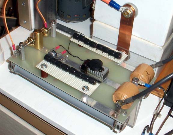
I incorporated the MOV’s as a final clamp before the NST and I moved the safety gap to the main gap-side of the resistors. The circuit is now what is often referred to as a “Terry Filter”. The placement of the safety gap is controversial, especially since this safety gap is in parallel with my main (SRSG) gap, which already has a 2-terminal safety gap in parallel with it. I constructed the Terry filter on a piece of blank G10, and used aluminum tape to create printed circuit-like traces between some of the components. Small bits of perf-board were used just for the MOV's. Fast-on terminals make the input/output connections. Here’s how it turned out:
A recent (May 2006) addition to the filter is a bi-metallic thermostat epoxied to one of the ZNR devices, to sound a battery-powered beeper should the ZNR's (MOV's) kick in and start to get hot. The thermostat (Stancor STC-120) closes at 120 degrees F. It feels just a bit obsessive, adding a protection circuit to a protection circuit, but no sillier than making sparks just "because".
And the circuit schematic: