Experiment to compare the AC resistance of primary inductors.
It has been observed that the innermost turns of primary coils will run
noticeably warmer than outer turns. The consensus on the Pupman Tesla List
is that this is due to the proximity effect, raising the AC resistance of the
inner turns, due to the stronger magnetic fields present there. I was
wondering if these losses could be minimized by a suitable choice of
conductor. Litz wire and ribbon come to mind, but I've never seen any hard
data comparing various primary conductors.
I was fortunate to have access at work to an HP4194 impedance/gain-phase analyzer,
pictured below, that can analyze AC resistance and inductance over a range of
frequencies. The photo shows the curves for inductance (essentially flat)
and AC resistance (sloping upwards) for the 14 gauge close-wound coil. The
cursor dots are at 600 KHz. All coils were hand-held during the test, not
on the concrete floor as pictured.
I constructed nine test primary inductors, most built with
similar geometry and inductance, but using different conductors. The
conductors I chose were:
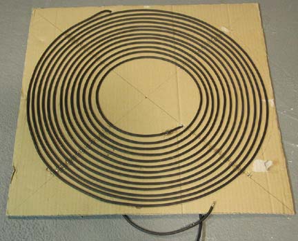
- 1/4" copper refrigeration tubing, the standard for Tesla Coil
primaries
- #7AWG-equivalent Litz wire, 259 strands of #38AWG enamel-insulated wire,
about 1/4" diameter overall Correction - The strands are #30AWG, not #38 as
the ebay seller had indicated!
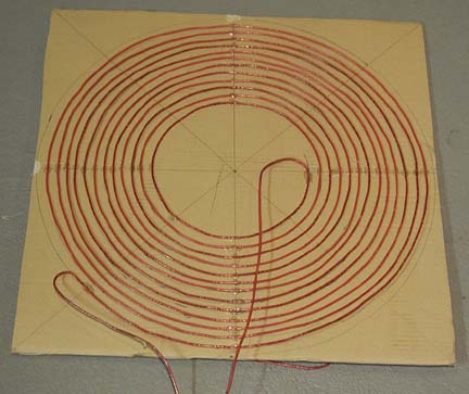
- #10AWG stranded wire, 105 strands of #30 tinned copper
- #14AWG solid wire
- 1/2" wide by .008" thick copper ribbon
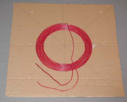
- 1" wide by .03" thick copper ribbon, donated by Resonance
Research Corp
- 0.10" thick solid aluminum "Ground" wire, Radio Shack #15-035
In addition to investigating what differences in AC resistance are due to
conductor choice in coils of identical geometry, I also created test coils to
determine the effects of geometry differences:
- Using 1/4" copper tubing, compare the single-layer 0.50" ctr-ctr
12.8-turn coil with a two-layer joined-at-the-center coil of 7.1 plus
7.25 turns, planes separated by
1.125", also 0.50" ctr-ctr. There were about 4 unused
turns beyond the tap points on each of the two sides..
- Using 14 gauge solid wire, compare a space-wound, 12.4-turn 0.50" ctr-ctr spacing
coil with a close-wound 0.115" ctr-ctr spacing coil
- Again using solid 14 gauge wire, a 2-layer 1/2" turn-turn
space-wound coil, 6.75 turns on one side, 6.5 turns on the other,
0.25" separation between sides, NO unused turns. (not pictured)
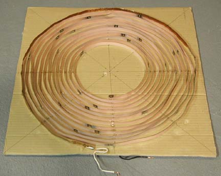
Except as noted, all were identically wound as flat spirals, inside radius = 4.0",
turn-turn spacing = 0.5", number of turns = 13. I tweaked the actual
number of turns to achieve a nominal inductance of 67 uH on all coils.
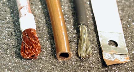
Litz wire, copper tubing, #10 stranded, and 8 mil copper
ribbon |
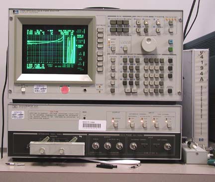 The HP4194 impedance/gain-phase analyzer The HP4194 impedance/gain-phase analyzer
|
|
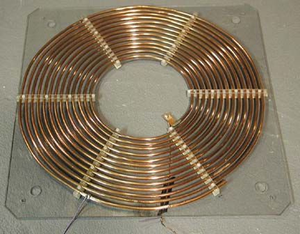
1/4" Copper tubing, single layer
|
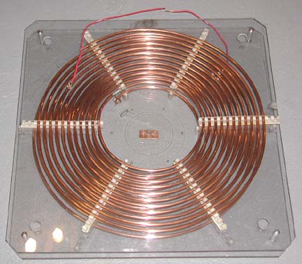
1/4" copper tubing, dual-layer
|
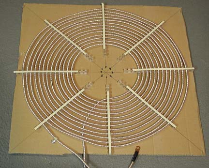
Litz wire |
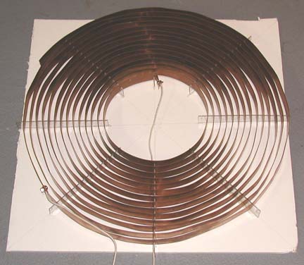
Solid #14 close-wound
|
#10 stranded wire |
Solid #14 space-wound |
|
.008" thick copper ribbon
|
.03" thick copper ribbon
|
Measured data, all resistances in milliohms. In order of ascending DC
resistance:
|
Rdc |
Rac
40 KHz |
Rac
80 KHz |
Rac
100 KHz |
Rac
200 KHz |
Rac
400 KHz |
Rac
800 KHz |
| Cu Ribbon, .030 thk |
13.3* |
150 |
204 |
212 |
336 |
495 |
707 |
| #7 Litz Wire |
21.7 |
113 |
156 |
185 |
367 |
841 |
1830 |
| Cu Tubing, 2-layer |
28.0* |
166 |
238 |
253 |
376 |
529 |
1027 |
| Cu Tubing, 1-layer |
33.7* |
148 |
192 |
209 |
294 |
431 |
547 |
| 0.1" Al wire |
51.2* |
208 |
289 |
297 |
445 |
670 |
1500 |
| #10 stranded |
53.3 |
209 |
303 |
320 |
520 |
847 |
1620 |
| #14 solid close-wound |
89.8 |
220 |
311 |
327 |
471 |
707 |
1040 |
| #14 solid 2-layer space |
109.5 |
222 |
313 |
322 |
476 |
713 |
1590 |
| #14 solid space-wound |
128.5 |
257 |
362 |
388 |
552 |
760 |
1060 |
| Cu Ribbon, .008 thk |
132.5 |
283 |
320 |
345 |
410 |
573 |
863 |
* Indicates that coil termination wires were not included in Rdc
measurements, but were included in Rac measurements.
Inductance was also measured at all data points but varied at most by 0.2uH.
Observations:
That the Litz wire was only marginally lower in resistance than the copper
tubing at low frequencies, and showed the highest resistance at high frequencies
was a real surprise! Yes, I am sure that this is in fact Litz wire with
individually insulated strands, and that all strands at both ends were stripped
and tinned together. I re-tinned one of the ends and took a second set of
measurements several weeks later with the same results. I was expecting that the Litz would be far superior
to the everything else, and that the inner turns of a complete primary inductor
could be wound with Litz. This might put the best conductor where the
losses are highest and still allow easy tapping of the outer turns, but it turns
out that copper tubing is pretty hard to beat, from cost, convenience, and
performance points of view.
I later found some great information on Litz wire on Cooner Wire's web site, http://www.coonerwire.com/Products/Litz/DesignD_2.html.
Their chart recommends strand wire
gauges as a function of the intended operating frequency. It indicates
that my 30 gauge strands would be appropriate for 1-10KHz, although my data
shows deteriorating AC resistance just above 100 KHz.
But I think we’re in the ballpark. So
I think the problem is not Litz wire in general, but rather the relatively
coarse strands of my particular Litz wire. If my Litz wire were made of
#38 strands as the vendor had indicated, things would probably have measured
very differently. Even so, for up to 100KHz, my #30-stranded Litz was the
best performer of all tested conductors.
The thin copper ribbon that I used was some very thin (.008") 1/2"
wide straps,
18" long, many pieces soldered together. The outermost 3/4 turn was
made of a double layer of 1/2" wide copper foil tape (thinner still), as I
was short a couple of strap segments. It may be that the skin (effect)
depth is greater than its thickness, so the performance may be limited by its
relative thinness. I believe that it fared as well as it did by virtue of
the fact that the adjacent-conductor spacing is nearly the full 1/2",
reducing the proximity effect.
I was surprised that the space-wound #14 coil had a higher AC resistance than
the close-wound coil. I was expecting that the close-wound coil would
suffer greater from the proximity effect and have a higher AC resistance, but
wrong! The close-wound coil used fewer feet of wire and so had a
comparably lower DC resistance, and the AC resistance was roughly the same
degree lower than the space-wound coil. This suggests that one should
space the primary turns as close as is practical.
The 1-layer copper tubing vs. 2-layer copper tubing measurements really
surprised me. The two-layer coil used slightly less tubing
so had a comparably lower DC resistance, but all AC resistances were higher -
about 120% in most cases, and much higher at 800KHz. Also, the measured
inductance of the two-layer coil was the nominal 65uH through 200KHz, but rose
to 66.7uH @ 400KHz, and to 74.5uH @ 800KHz. All single-layer coil
inductance measurements were flat across all frequencies. The thing that
was different for the two-layer coil is that both top and bottom coils were 11
turns, tapped at 7 turns, so there were four unused turns at each end of the
coil. It would have been interesting to have tested a true 7-turn &
7-turn two-layer coil but I wasn't eager to slice up my primary.
To determine whether the unused turns were responsible for the poor
performance, I constructed a 2-layer coil of #14 solid wire, but with no unused
turns. At 200 KHz and below, the 2-layer coil had a very similar
resistance to its 1-layer counterpart, but beginning at 400KHz, the 2-layer AC
resistance really began to soar, just as with the 2-layer tubing coil. The
inductance of the 2-layer coil did increase from 66.5 uH (at all frequencies to
400 KHz) to 68.1 uH at 800 KHz. But the puzzling thing is that with the
1/4" tubing, the 1-layer coil had the lower resistance (over all
frequencies), while with the #14, the 2-layer coil had the lower resistance
(until somewhere above 400 KHz). Not sure what to conclude...
The .03"x1" copper ribbon had the lowest DC resistance of all test
coils and I would have expected it to have the lowest AC resistance by virtue of
its greatest spacing between turns. But instead, its AC resistance was
just slightly higher than the 1-layer copper tubing coil, across all
frequencies. Two thoughts come to mind: The tubing was recently
steel-wooled to a bright finish, whereas the ribbon had a dull brown
patina. Perhaps the oxidized surface where the skin effect currents flow
is responsible for the higher resistance. Or more likely, the wider ribbon
conductor promotes eddy currents and their losses, much like the way
thinner Litz strands would have lower losses.
That the stranded #10 wire fared so poorly is no surprise. I often hear
people suggesting the use of coaxial cable with a braided shield as a primary
conductor, and I wanted to demonstrate that stranded conductors are a poor
choice, despite having a low DC resistance.
The Aluminum wire fared reasonably well for most typical Tesla Coil
frequencies. I often hear advice saying that aluminum wire is utterly
unsuitable for use in a Tesla coil, due to the skin effect forcing the surface
currents into the outer oxide layer. I think this is not so, at least for
reasonable TC frequencies. Up through about 400KHz, the AC resistance
stayed about 50% higher than that of the copper tubing. I would conclude that if
the aluminum conductor were heavier (to equalize the DC resistance),
that its performance would be comparable to the copper tubing, up to 400KHz.
Of course, there are other very good reasons to select a copper primary over an
aluminum one - the ease of soldering/splicing copper tubing, and the better
integrity of a clipped-on connection to a copper conductor.
Some questions were raised in my earlier testing about whether unused outer
turns resulted in measurements indicating greater losses. When I tested
the aluminum primary, I also made two additional measurements. I
constructed a 5-turn coil of #10 wire with the same OD as the aluminum primary.
Without the extra 5 turns, the coil is the nominal 67uH. If the 5 turns
were added, more or less on top of the outermost turn of the Al coil, the
inductance rises to 150uH. I made one test with the 5-turn coil in place
but with neither end connected. The other test had just one end of the
5-turn coil connected to the outermost turn of the Al coil, and the other end of
the 5-turn coil unconnected. The table below is what I measured:
|
Rdc |
Rac
40 KHz |
Rac
80 KHz |
Rac
100 KHz |
Rac
200 KHz |
Rac
400 KHz |
Rac
800 KHz |
| 0.1" Al wire |
51.2* |
208 |
289 |
297 |
445 |
670 |
1500 |
| w/ 5-turn coil n.c. |
51.2* |
211 |
295 |
311 |
451 |
720 |
1650 |
| w/ 5-turn coil connected |
51.2* |
231 |
310 |
314 |
475 |
754 |
1990 |
It does appear that the presence of unused outer turns results in slightly
higher resistance at reasonable operating frequencies, and significantly higher
resistance at very high frequencies.
Conclusions:
1/4" copper tubing is a very good choice for primary coils. I'd
recommend using the closest spacing possible. Do not under any
circumstances use stranded or braided wire. Unresolved is if, and to what
degree, unused outer turns and two-layer construction affect the AC
resistance.
Also note that while this study gives definitive rankings to the AC
resistance of various conductors and geometries, the actual impact to one's
Tesla coil's performance was not addressed. It may be that spark gap
losses are so far in excess of primary losses that the actual impact of
conductor choice is negligible. Or quite possibly not.
Back to Gary Lau's
main Tesla Coil Page