
Power Factor Correction capacitors, or PFC caps, may be used to reduce the AC current drawn from the wall or variac. While they won't affect performance one way or another, they may prevent fuses or circuit breakers from blowing or tripping. A PFC cap is placed in parallel with the primary winding of one's power supply transformer.
With my .02uF tank capacitor, my 15KV/60mA NST now draws over 20 Amps from my (15A) variac, and no doubt more from the wall, and this isn't counting the current for the vacuum cleaner motor. The 20 Amp circuit breaker often trips if I run the coil for more than a continuous minute, so I need to do something.
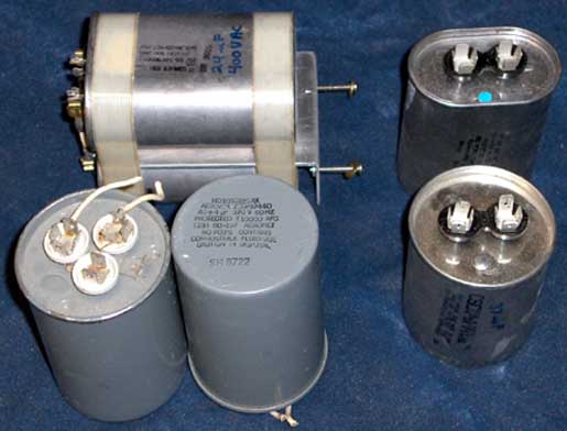
A PFC cap needs to be an AC-rated capacitor. Motors often use two types of AC capacitors. Motor START capacitors are energized only while the motor is accelerating or starting, and these caps are not rated for continuous duty. They have electrolytic dielectrics, and will get hot and vent if the rated voltage is applied continuously. They often have capacitances specified in ranges, like 41-53 uF, and this should be a clue that they are not suitable. Also a clue is the notation "For Motor Starting" visible on the cap below. The All Electronics catalog advertised a 30-36uF 330VAC "polypropylene" capacitor. I bought some and it turns out that these are electrolytic, not polypropylene. Below is another example of a capacitor that is NOT suitable for PFC use:
Motor RUN capacitors on the other hand are rated for continuous duty and are suitable for PFC
caps. Below are several run caps that are suitable for PFC use:
OK, so how much capacitance is needed? I'm still working that one out. With a static spark gap, the AC current draw is extremely erratic. Using a 20 Amp analog meter with my 88 uF PFC cap, the meter was mostly pegged, but also regularly swung down to 15-16 Amps. Adding one of the 135 uF caps brought the needle mostly below 20 Amps, swinging as low as 12-15 Amps. Adding the second 135 uF cap was inconclusive since the meter was still so erratic. Experiments continue to determine the optimal value. Stay tuned…
Switching to a synchronous gap with a steady 120BPS break rate makes the mains current measurement much more stable. I scored a couple of 120uF/250VAC motor run caps on ebay, and now use these for PFC. I tried using zero, one, and two of these caps in parallel with the NST primary, and the lowest mains current occurred with the 240uF, so that's what I use.