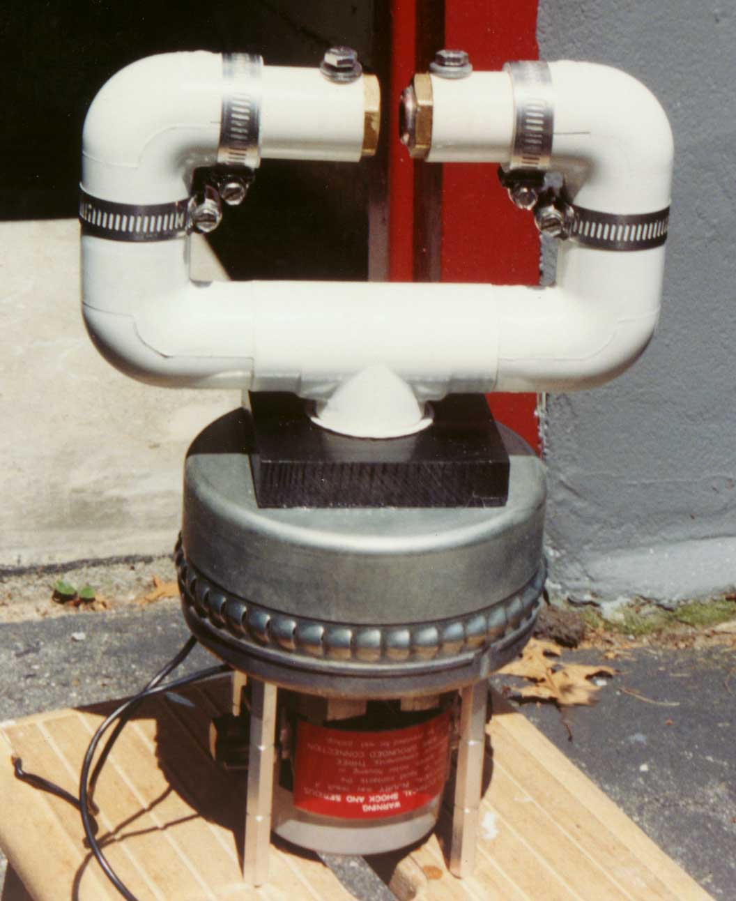
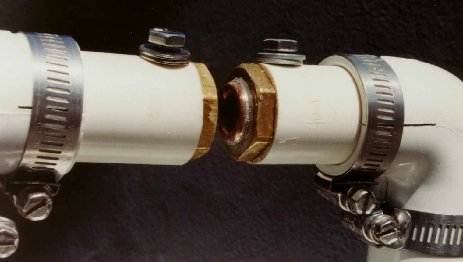
Here is my single segment static spark gap. I use a vacuum cleaner motor to create powerful airflow through the spark channel. Gap distance is 0.36 inches. The gap electrodes are brass plumbing reducers, and on one of them, I’ve soldered a half-torus shaped piece of copper wire (see detail below) to encourage the arc to form towards the center of the electrodes, where the air velocity is highest. I had been using a separate variac to power the vacuum cleaner motor. With no airflow, performance is terrible. If the variac delivers 24VAC or above, then performance is excellent and better than my RQ 12-segment static gap. No improvement was seen going above 24V, so I've since replaced the variac with a 5 Amp off-the-shelf triac-based lamp dimmer. Update 7-11-99 - The dimmer shorted out, not sure why. Perhaps I did need a more beefy dimmer, or maybe a snubber network across the dimmer.
I bought the vacuum motor from American Science & Surplus, www.sciplus.com. Sometimes it's listed in their catalog for $12.50, sometimes it's not listed at all. When it's listed, the catalog says it draws 3A @120VAC and 8A @220VAC. That's nonsense. I measure over 10 Amps @120VAC, and it sounds like it's about to explode.
I performed an experiment to better observe the arc geometry in this gap. By disconnecting the tank components and having the NST output arc directly into the gap, the arc runs at a much lower current, and is less brilliant and safer to look at. The result was not at all what I expected. Rather than forming a ring between the two reducer faces originating at the copper half-torus, 95% of the arc was in a slender line precisely centered in the holes through the brass reducers. I couldn't see where this line of arc terminated so I replaced one of the PVC pipes with a clear acrylic pipe. The arc did not extend beyond the downwind (closest to the vacuum motor) end of the reducer (not surprising), but did stay centered throughout the fitting. The connection between the arc and the fitting was also surprising. The best way to describe it is like a bottle brush. The main arc travels down the center of the brass reducer, like the handle of the brush. Then, the arc connects to the reducer through a very large number of much smaller arcs, perpendicular (or nearly so) to the main arc, like the bristles of the brush, over the length of the reducer.
While I continue to be satisfied with the performance of this gap, this observation makes me wonder if it would have been better to have air blowing through the gap, rather than sucking. The air pressure in the area of the arc is at a much lower pressure than ambient, and this low pressure air would have a lower breakdown voltage per length. So, for a given gap breakdown voltage, this gap would have a longer arc than one with atmospheric or higher air pressure, with possibly higher losses. It would be interesting to compare performance with the airflow reversed, although the vacuum cleaner motor doesn't easily lend itself to this configuration. A blowing version of this gap would have some other problems as well, like the arc wanting to blow towards the outer perimeter of the reducer faces, where the air velocity is at a minimum. Perhaps if I had enclosed and blown air into the area outside of the reducers…
I recently (7-11-99) tried adding my .01uF Fair Radio Sales cap in parallel to my .011uF MMC, for a total tank capacitance of .021uF. This is twice the value required for 60 Hz mains-resonance. With this new cap value, several things increased. Most notably, spark length increased from 51" to 58". The current drawn from the wall also increased, as evidenced by the 20 Amp breaker tripping after about one minute of run time. This while using 88uF of PFC caps. With some new AC ammeters, I was able to see that the NST primary current is extremely erratic, and pegged my 20 Amp meter. Most surprising of all, the NST secondary current was about 225 mA! This from my 15KV/60mA NST! Granted, the meter is calibrated in RMS volts for a sinusoid and the NST charging current is far from that, but still, it must be in the ballpark.
I also tried scoping the capacitor voltage. John Freau tipped me off as to the technique to do this. Since neither side of the cap is grounded, I referenced the HV probe to the NST case, and assumed that the voltage on either side of the cap represents one-half of the total voltage across the cap. If both sides of the NST are reasonably identical, I believe this is a valid assumption.
With my single gap set to 0.34", the cap charging voltage and gap breakdown voltage was 24KV.
With my single gap set to 0.25", the cap charging voltage and gap breakdown voltage was 20KV.
With my single gap set to 0.185", the cap charging voltage and gap breakdown voltage was 14.4KV.
I noted that when the variac was set to roughly 60%, the NST primary current often settled to a non-chaotic minimum of roughly 10 Amps, and the arc and gap noise became much more uniform. Scoping the cap voltage, I was able to see that the system was now operating an even 60BPS. Sometimes the cap would fire on the positive peaks, then it would shift and fire on the negative peaks. Spark performance at this reduced power level was nothing to write home about though.
Cranking up the scope sweep speed, it was clear that my single gap does a very poor job of quenching. I could count at least 4-5 notches on the capacitor voltage. This is probably why my caps (both MMC and Fair Radio Sales) get warmer than others have reported. A system that quenches on first notch places much less stress on the cap than such a poorly quenching system. This may also explain why I blew my extended foil rolled poly cap. It may have survived with a better quenching gap. But the poor quenching of a single gap appears to be offset by lower gap losses, resulting in very acceptable performance, at the expense of giving my caps a real beating.
Back to Gary Lau's main Tesla Coil Page