I have had it with blowing rolled poly caps! So far, two down, no survivors. And the dollar and labor cost costs of these were not small. While my Fair Radio Sales commercial cap continues to work, it does get warm after less than a minute of run time, so I have doubts about being able to run it for extended periods. Based upon the reported success of others, I have built a new tank capacitor using a large series-parallel array of small, commonly available commercial capacitors. So far I have logged over 15 minutes of near-continuous run time on this new capacitor and it continues to run, getting only very slightly warm, much less so than any of my other capacitors. Spark performance has been identical to both my FRS and rolled poly caps.
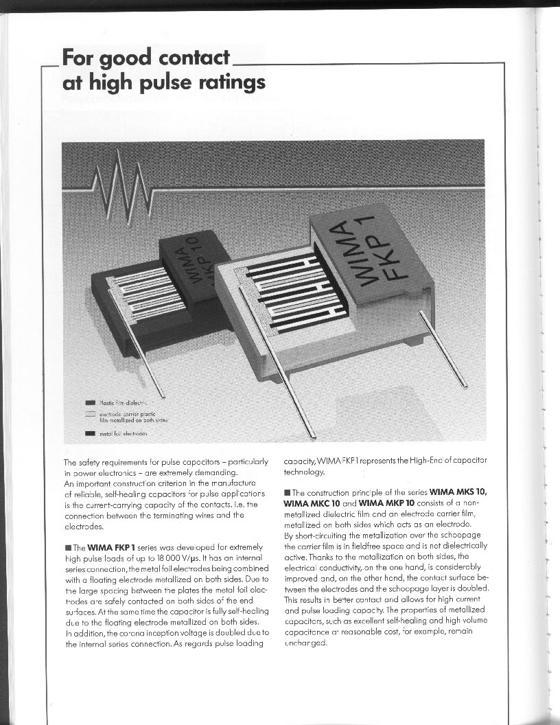
The array is made from Wima brand, series FKP-1, polypropylene dielectric capacitors. The catalog describes these as: Polypropylene capacitors for pulse applications with metal foil electrodes, internally series-connected for very high current ratings. For extremely high pulse ratings because of metal foil electrodes and metal sprayed end-surface contacts. Self-healing - internal structure. Extremely low dissipation factor. High insulation resistance. Low dielectric absorption. Sounds like just what the doctor ordered!
The component device I used was a 0.015uF, 1600VDC unit. I made strings of 16 of these in series, so each string has a DC voltage rating of 16 x 1600V = 25.6KVDC. Each string had a capacitance of 0.015/16 = 0.0009375uF. Wiring twelve of these strings in parallel yielded my target capacitance of 0.0112uF. So I used a total of 16x12 = 192 capacitors.
I ordered the caps from All Electronics, www.allcorp.com. They were listed in the catalog for $0.75 each, but since I ordered 200 of them, they let me have them for $0.60 each. Watch out, there were some very similar looking but wrong-valued caps mixed in with them! They had 300 on hand when I ordered them, I can't say what's left. They also have another polypropylene cap, .015 uF @ 1500VDC, listed as "THD 23-3", their part number MKP-0155, for $0.85 each. I don't know anything about this one.
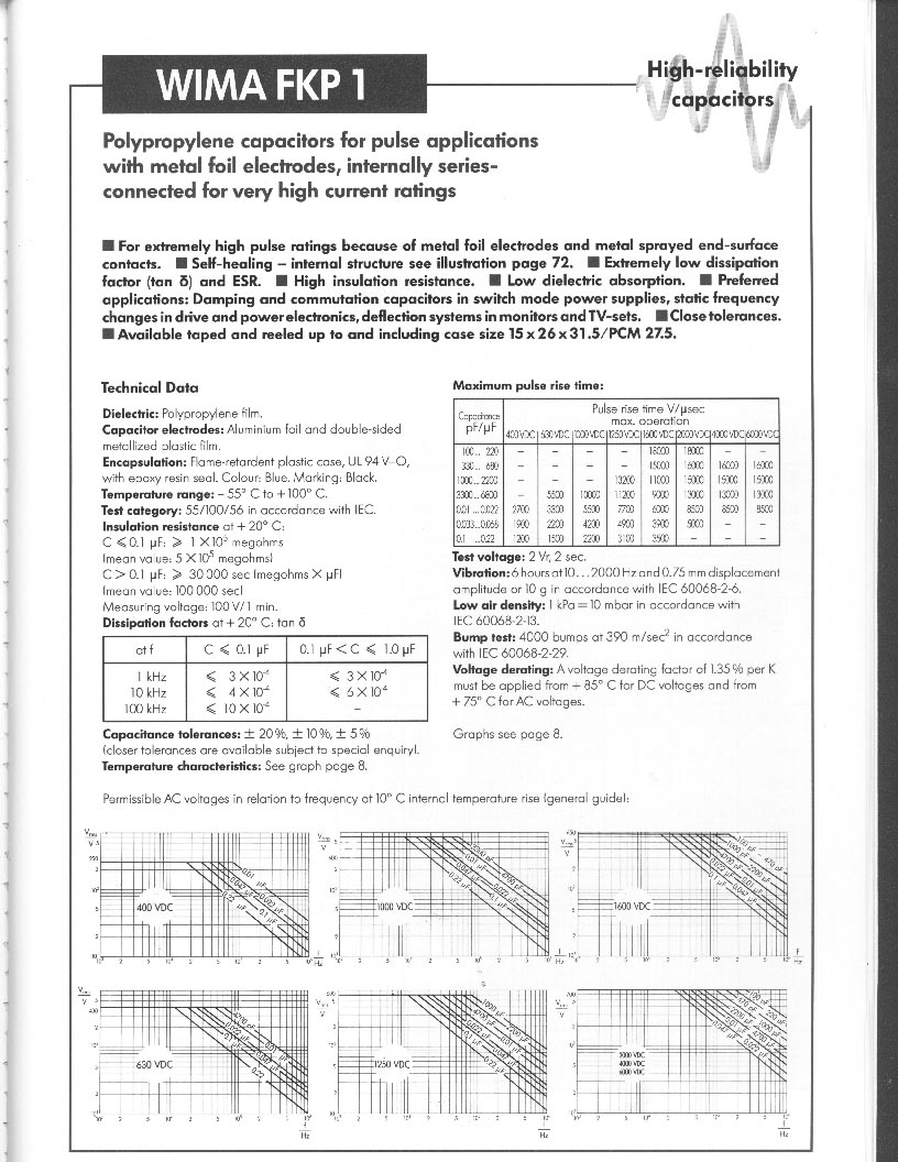
I'm using this capacitor with a 15KV-RMS NST power supply, so the peak voltage will be something like 21KV. (Note, this is an invalid assumption, see my Single Gap and Pspice simulation pages.) However, the individual capacitors are marked 1600VDC/500VAC. Last time I checked, I was using AC, not DC. Further, the Wima catalog shows dielectric strength derating curves that relate the normalized dielectric breakdown voltage rating to operating frequency. At 200KHz, a polypropylene dielectric will only have about 30% of its DC voltage rating. So it looks like despite my success, the cap manufacturer would tell me that these devices are being used far beyond their published ratings. If you choose to make a similar cap, don't say I didn't warn you.
Here is the way I wired these caps up:
The thin vertical cross-linking connections should, in theory, not be necessary. It was originally my intent to add 6 meg bleeder resistors across each set of 5 or 6 paralleled caps. While it has been suggested that such resistors serve to equalize the voltage across each of the 16 series caps, I believe this wouldn't accomplish that, as the resistance of the resistors is very high compared to the AC impedance of the caps. Only the 16 series caps being the same value can guarantee an equal division of voltage.
It has also been suggested that such resistors would prevent the accumulation of a DC bias across some of the capacitors that, which combined with the normal AC voltage component, might exceed a cap's voltage rating. While resistors would accomplish that, it's not clear that such a DC bias could actually develop, especially in a coil with an AC power supply.
Resistors across each of the series caps would also guarantee that after power is shut off, that there is no way possible for any residual , hazardous voltage to be left in the cap - a personal safety measure. It was my intention to add 6 meg resistors across each of the cross-linked series elements for this purpose. But the truth is, I was so anxious to see if it worked, that I just didn't get around to it.
Note - These photos show only eleven strings installed. I saw no reason not to use the 12th string since I had the caps.
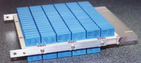
Above is my completed capacitor. I made it on two pieces of G10 perfboard, one with six strings, and the other with five (six). All strings are wired in parallel.
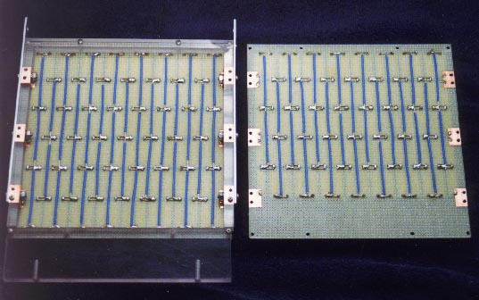
Above shows the internal connections. The blue insulated wires are the cross-links between the strings.
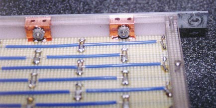
Above is a detail showing how I made connections between the perfboards and the aluminum bus bars. The end points of the cap strings are soldered to some adhesive-backed copper foil tape on the perfboard. The 1/2 inch x 3/8 inch lexan spacer running horizontally above also has copper tape that makes contact with the two perfboard assemblies, as well as with the aluminum bus bar.
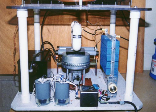
Here's my MMC cap installed in my coil. Nice and compact!
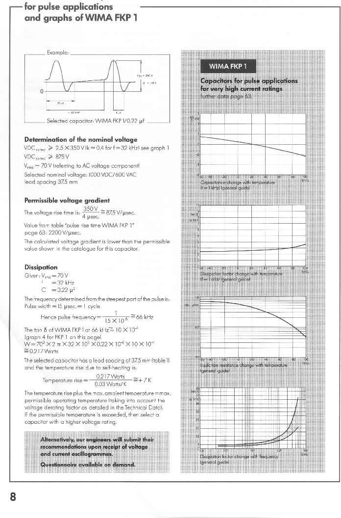
Lastly, here's some pages I scanned from the Wima capacitor catalog, detailing exactly how to use the voltage ratings:
Wima_selection_1.jpg shows how to determine the maximum voltages and currents that may be applied to a capacitor.
Wima_selection_1detail.gif is a close-up of the graphs on the previous page. Of particular interest is the graph showing what the effective dielectric strength is as a function of operating frequency.
Wima_selection_2.jpg is a continuation of the first page.
Wima_specsheet_1.jpg shows the construction of the caps and briefly describes some of the pulse cap family properties.
Wima_specsheet_2.jpg gives the AC and DC specs for the FKP-1 series.
Wima_specsheet_2detail.gif is a close-up of the graphs on the previous page.
Back to Gary Lau's main Tesla Coil Page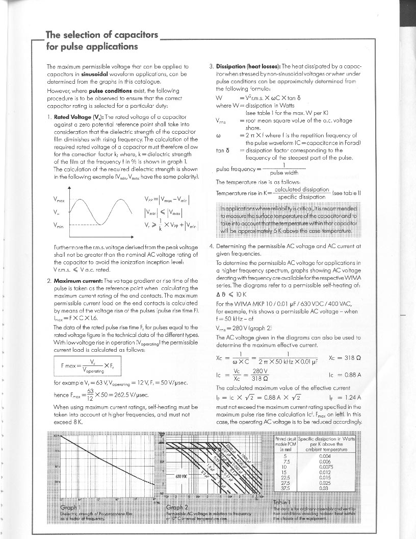