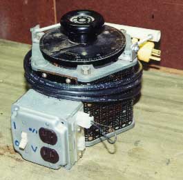
This is my 15 Amp 0-140V variac - a $12 MIT flea market acquisition. I added the electrical box. In it is a negative temperature coefficient thermistor in series with the input that eliminated input current surge. Rcold=1.0 Ohm, Rhot=0.015 Ohm. There are two connectors on the right side. The top one is a two pin connector that is usually shorted. It is a current loop for monitoring the variac output current to the NST. The lower three pin connector goes to the Tesla Coil. The pins are: variac output to the NST, neutral, and switched 120VAC for the vacuum cleaner motor or RSG motor. Note that AC ground is not connected to the coil, although it is connected to the variac chassis.
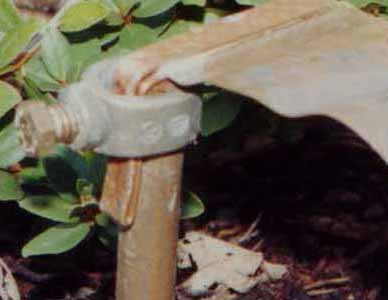
Here's the tip of my 8 foot ground rod, with the ground strap connected. The ground strap is a 2-inch wide by 12 foot length of copper roof flashing (Home Depot), cut into 2-inch strips, soldered together. The "L" shaped terminal at the end of the strap is a length of 1/4" copper tubing, flattened, and soldered to the strap.
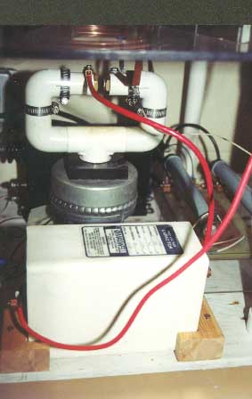
Here's a closer look at the hookup of things, in particular the tank components. The red wire from the gap to the right side of the capacitor is finely stranded #6AWG. The connection from the right-hand gap connection to the inside turn of the primary is accomplished with 1/2" wide copper strap. The cap is my .02uF 45KV (p/n 37093) Maxwell.
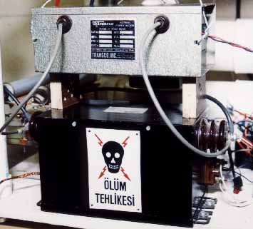
These are the two Neon Sign Transformers (NST's) that I own. The upper one is 15KV/30mA, and the lower one is 15KV/60mA. I normally just use the 15/60 unit, the other is just shown for comparison, although I'm sure that running them in parallel as shown would improve performance even further. The sign on the lower unit is a photo I took in Turkey. I have it on good authority that it translates to "Danger of Death", although the message is clear regardless of the words. Much cooler than your usual "Danger High Voltage" signs!
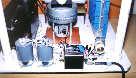
Above is a view of the 120VAC side of my coil. Leftmost in black is my 15KV/60mA NST. Back-row center is my vacuum cleaner motor for the spark gap. Back-row right is my MMC tank capacitor. Front-row left are two 44uF 370VAC power factor correction caps. Using these will reduce the power factor of the NST, resulting in a lower current drawn from the wall, though not affecting performance either way. I have since upgraded to a pair of 120uF 250VAC caps, for a total of 240 uF. Front-row center is a 30 Amp EMI filter, hopefully reducing some of the RF nasties before they find their way into my house wiring. Not really visible but hanging off the right side of the EMI filter are an additional line filter capacitor and a Metal Oxide Varistor (MOV) as a last line of defense against AC spikes before going off to the Variac and wall outlet. Front-row right is a household 5 Amp triac-based lamp dimmer to throttle down the power to the vacuum cleaner motor. Although the motor would draw over 10 Amps at full power, the 5 Amp dimmer does fine since I only need to run it at a fraction of full power. The three wire AC cord at bottom right goes off to my Variac, but it is terminated with a special plug. I want the NST to see 0-120% from the Variac, but I want the vacuum motor & dimmer to always see 100% power. Since a Tesla coil doesn't use the 3rd wire ground, I designated the 3 wires as: Variac-hot (to NST), 120V-hot (to dimmer), and neutral.