It is ccommon practice to include an EMI (Electro Magnetic Interference) filter between the NST primary and the variac or mains power connection, to hopefully reduce the magnitude of the voltage spikes and other interference that makes its way into your household wiring. It has sometimes been suggested to connect the filters backwards from the intended configuration. I recently had an experience that makes me doubt the validity of this "backwards" advice.
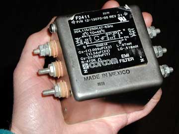
I had been using a Corcom 30 Amp EMI filter (above) ahead of my 15kV/60mA NST for well over a year. I recently replaced the primary, secondary, and toroid with different ones, so I had to experimentally tune for optimum tap point. Shortly after I started, the coil's output diminished, the circuit breaker tripped, and the garage was filled with an evil smell. It turns out that my EMI filter had toasted. While my NST will pull up to 20 Amps from the wall, I couldn't believe that it could over-current and cook a 30A filter, and do it in less than 60 seconds. It must have been an over-voltage problem with one of the filter's internal caps.
I looked at the complete circuit, with this model of what it is that the filter is trying to accomplish. For this discussion, I'm going to assume that the problem is that there is inductance and resistance between the base of the Tesla secondary coil and the "true" earth ground. This will result in voltage spikes between the secondary base "RF ground" connection, and the 3rd wire earth ground that my fusebox is connected and referenced to.
Figure 1 below shows the circuit if the EMI filter is hooked up "backwards", or with the LINE terminals connected to the NST. This is how my filter was hooked up. Normally the case would be connected to the 3rd wire ground, but since I didn't have a connection to this available at my coil, and since the metal case was a potential streamer strike-target, I also connected it to the RF ground network.
Notice how the RF voltage on the RF ground is being applied directly across C7 and C8 to the mains terminals! I've not yet performed a post mortem but I'm guessing that its these caps that blew. The common mode chokes L3 & L4 are doing nothing.

Figure 2 below shows a slightly better (or at least less destructive) way to connect an EMI filter, if the filter must be mounted at the NST as mine is, and a 3rd-wire ground connection is unavailable. Since the NST case is already at RF ground potential (with HV RF spikes relative to earth ground), C2 & C3 see no such spikes. Common mode chokes L1 & L2 are now able to perform their intended function of keeping the RF to their "right" and away from the variac and mains connections. But it would probably also be a good idea to add a pair of suitably rated caps like C2 & C3 between the variac hot and neutral connections to 3rd wire ground, at the variac. Without them, the filter is not wired to form a functional low-pass filter. I don't think that the RF ground connection to the case contributes anything.
If one were to locate the EMI filter at the power control box, it would then have access to the 3rd wire ground, and the Figure 3 circuit could then be used. This is the best and recommended configuration for an EMI filter.
Having said all this, it's not at all clear exactly what it is that we're trying to filter out. If the really "bad" stuff is at the frequency of the tank circuit, that may be as low as 78 KHz (in my case), and most EMI filters are not intended to attenuate such a low frequency. There is no doubt a good deal of energy is generated throughout the RF spectrum, and an EMI filter is probably good at attenuating much of that. But sadly, I'm not aware of anyone attempting to make any quantitative measurements of "stuff" coupled into the mains lines, and exactly how much such a filter attenuates it. Another thing for my growing to-do list...