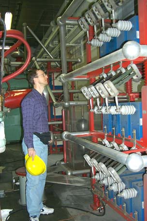
I recently had the pleasure of a private tour through the MIT Bates Linear Accelerator
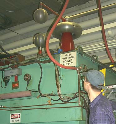
The two spheres are a safety gap, just like the ones we use (right?) on our NST's. The red cone just below the toroid is the HV output. The toroid is there for field control around the junction where the safety gap connects. The pipe going off to the right from the toroid is the HV bus going to the capacitor banks.
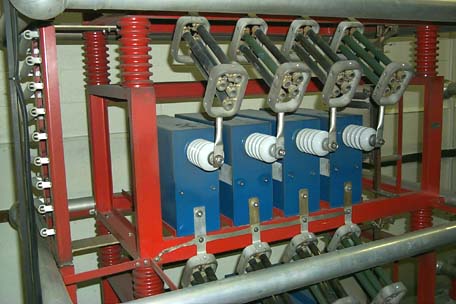
Pictured below is one of two capacitor banks that is across the output of each of the HV supplies. Each of the twelve blue caps is 0.66uF @60KV, and they are connected four in parallel, and three in series, for a total value of 0.88uF @180KV per bank. For the two banks combined, that's 28,512 Joules! Compare that to the 4.9 Joules of my MMC. The resistors in series with the individual capacitors are there to limit the current in the event that the crowbar circuit trips, providing a safe place for the charge to dissipate.
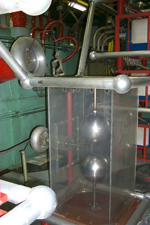
In the event that a problem is detected with the klystrons (like they won't shut off after the end of their pulsed "on" time) and it is judged to be a bad thing to have the klystrons powered up, there is a crowbar circuit to dump all of this energy in the capacitor bank in a hurry, rather than have it destroy the very expensive klystrons. Pictured below is a triggered spark gap. The upper sphere in the enclosure is connected to the HV rail and the lower one to the HV return. Midway between them is a needle that is resistively biased at one-half of the HV potential. If a fault condition is sensed, the needle is grounded.